Page 4 of 5
Posted: Mon Dec 27, 2010 4:35 am
by ScottaKR
falconman wrote: But now I can do final assembly of the crank and complete this project in about 2 months. [-o<
So does that mean it's finished now?


Just been going over this project after TSI gave me some bad ideas (well bad for my bank ballance anyways

), and couldn't find mention of what year the barrels your useing are for.
Posted: Mon Dec 27, 2010 9:51 pm
by falconman
Unfortunately I bought another house not too long after that post. Anything that requires spending money is on hold. I was able to move some things out of the garage to the new house so I actually have room to work. It has been raining a lot here lately and I was planning on bringing the press inside for the next few days of rain and assemble the crank. After that, depends how much the machine shop wants to drill the new stud holes. The cyl kits I used were these:
http://www.moto-man.com/Athena-Works-Cy ... _4470.html
Posted: Mon Feb 21, 2011 9:27 am
by falconman
I'm assembling the crank now but the spare I was going to use as a guide is at the other house. Does anyone know how to orient or phase the gear on the crank for the balance shaft? From what I remember the dot on the gear is 90 degrees from the rods but does it matter which cyl is up or down?
Posted: Mon Feb 21, 2011 10:35 am
by ScottaKR
falconman wrote: but does it matter which cyl is up or down?
It most definately does. Haveing it the wrong way would make it worse than running withiout a balance shaft at all. Another member's crank had been built with it's gear 180deg out and it ran as rough as heck.
Balancer shaft
Posted: Tue Feb 22, 2011 2:03 am
by KR-1R
.
.
Courtesy of JANBROS...

at Left cylinder Top Dead Centre - crank punch mark(s) forward
Posted: Tue Feb 22, 2011 3:15 am
by falconman
I had figured the balance weight had to be 180 off from the rod (of the same side). But what I'm not sure of is the dot on the tooth or the dot on the valley 90 degrees off from the rods? I bet the engineer that designed this asymmetrical dot system is still laughing his ass off.
](./images/smilies/eusa_wall.gif "Brick wall")
Looks like I will have to guess and try to make the balance weight as close to 180 as possible. Thanks for the pic, it does help. =D>
Posted: Tue Feb 22, 2011 4:16 am
by KR-1R
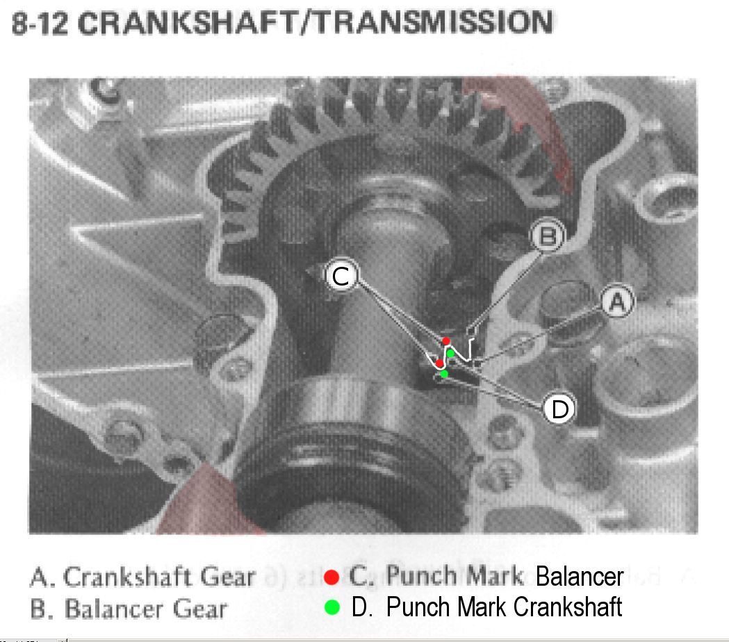
crankshaft punch mark (on tooth tip) will fall into balancer root mark
balancer tooth mark should fall into crankshaft root mark
Posted: Tue Feb 22, 2011 4:55 am
by falconman
I had printed that out. It wasn't clear enough. I already pressed it together. Just set it up to where the weight on the balance shaft was 180 degrees from the rod pin. If it needs adjusting I can do that on the balance shaft gear. Also just fyi, when test fitting the crank I found that the outside of the crank halves needed to be chamfered or the crank rubbed on the cases. I'll finish truing it tomorrow then clean the cases to weld them.
Posted: Tue May 31, 2011 6:06 am
by falconman
Posted: Fri Sep 02, 2011 11:58 pm
by Mark66
Hi Falconman. I was pointed in this direction when I asked about increasing capacity on a KR1/S and have a question . Why did use the RZ crank parts rather than offset crank pins ?
Posted: Sun Sep 04, 2011 5:02 am
by falconman
There is no way to modify the stock crank to increase stroke and the RZ crank seemed to require the least amount of machine work. The pins are not removable on the KR crank.
More info on crank -
viewtopic.php?t=4235&highlight=
Posted: Mon Sep 05, 2011 11:21 pm
by Mark66
Is there no way of adding metal to the pins and regrinding ? I remember an article in a car mag years ago about a company doing a similar thing with camshafts in order to re-profile them . They used a form of welding that added metal to the rotating part and building it up to the required thickness. Was a while ago right enough and dunno if it would stress the metal too much. Sorry if these are stupid questions. Don't ask, don't learn. The sheer amount of effort you have put into this did get me wondering what I was missing

. Even at 45, every day is a school day. Nice work by the way.
Posted: Tue Sep 06, 2011 12:18 am
by falconman
I have never heard of that technique being used that way before. Only as you stated, to profile cam lobes. What little experience I have with welding tells me the heat involved would change the tempering of the crank throw plus the way the throw is cast may not be optimal to support an offset pin that way. Someone more experienced in welding/machining would be better suited to answer that question. I'm 50 and still learning. I just hope I learn enough in time to build a bike that breaks 200 before I'm too old to enjoy it anymore.
Posted: Sun Aug 19, 2012 1:28 am
by JanBros
So Jim, almost a year has past, any news ?
Posted: Wed Sep 05, 2012 3:06 am
by falconman
No, still waiting for the shop to make the new throw.