You really need both.
You get det damage on the top mating face of the barrel behind the nicasil.
If you look at the heads in the above post, the outer flat section of bronze/brass is there for this reason.
The heads lift and flame travels in this area. I have seen head bolt upgrade reduce this, keeping squish constant instead of opening up, allowing leaner jetting prior to detonation.
This isn't really related to a kr though....
Squish clearance and compression ratio - advice please!
-
gangus

- Smoker
- Posts: 55
- Joined: Tue Mar 22, 2011 10:11 am
-
James P

- Oil Injector
- Posts: 582
- Joined: Mon Mar 11, 2013 10:47 am
- Location: Sydney, Australia
Re: Squish clearance and compression ratio - advice please!
After procrastinating for ages on this, I decided to get something done. I made a few measurements and did a few calculations to see how much the port durations would be reduced by lowering the cylinders:
Kawasaki specification:
Exhaust 186deg
Transfer 126deg
Comp ratio 7.4:1
My measurements and/or calculations (standard engine with standard gaskets etc.):
Exhaust main 179.5deg
Exhaust aux 188.5deg
Transfer 127.5deg
Squish clearance 1.25mm
Comp ratio 12.2:1 geometric, 7.4:1 corrected
If I reduce the squish clearance to (for example) 0.85mm by using thinner base gaskets, I should obtain:
Exhaust main 177deg
Exhaust aux 186deg
Transfer 124deg
Squish clearance 0.85mm
Comp ratio 13.3:1 geometric, 8.1:1 corrected
This seems OK to me, although the compression ratio is higher than I'd like - I would prefer to keep the standard (or very slightly lower) compression ratio for reliability with today's questionable fuels. I have therefore had the combustion chambers enlarged by between 1.0 and 1.5ml (each one was milled identically, but my syringe only indicates to the nearest half millilitre!).
If I can obtain exactly 0.85mm squish clearance, the new compression ratio should be about 11.7:1 geometric, 7.2:1 corrected.
The cylinder head in the mill with one combustion chamber roughed-out, ready to start the second one:
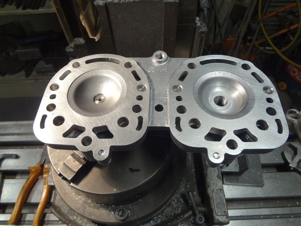
I would have liked to have had the squish bands recut to match the piston crowns exactly, but decided that it would be too much faffing about (possibly needing to skim the head as well), for perhaps questionable advantage.
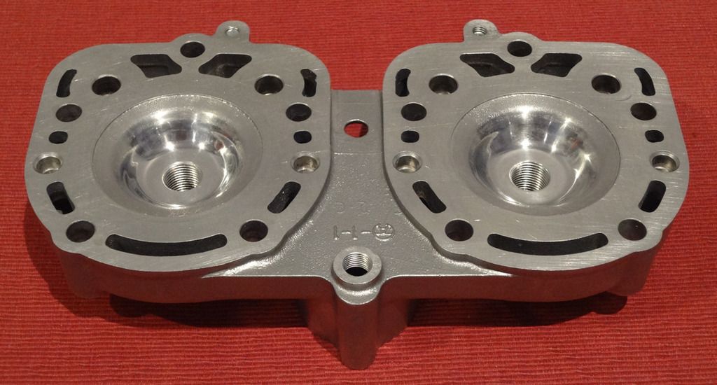
Job done, combustion chambers lightly polished:
Scan of a direct tracing of the combustion chamber profiles, before and after:
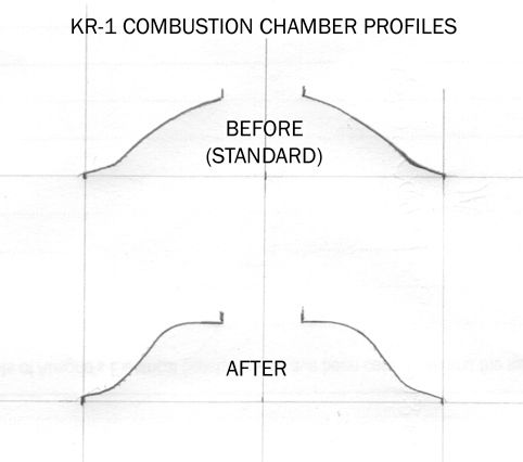
For some reason the inner edge of the squish band looks a little different on each tracing. However, no modifications were done in that area.
Now I'm just waiting for the arrival of thinner base gaskets from Dan McBryde. Dan has posted them, so they should be here this week or next.
Regards,
James
Kawasaki specification:
Exhaust 186deg
Transfer 126deg
Comp ratio 7.4:1
My measurements and/or calculations (standard engine with standard gaskets etc.):
Exhaust main 179.5deg
Exhaust aux 188.5deg
Transfer 127.5deg
Squish clearance 1.25mm
Comp ratio 12.2:1 geometric, 7.4:1 corrected
If I reduce the squish clearance to (for example) 0.85mm by using thinner base gaskets, I should obtain:
Exhaust main 177deg
Exhaust aux 186deg
Transfer 124deg
Squish clearance 0.85mm
Comp ratio 13.3:1 geometric, 8.1:1 corrected
This seems OK to me, although the compression ratio is higher than I'd like - I would prefer to keep the standard (or very slightly lower) compression ratio for reliability with today's questionable fuels. I have therefore had the combustion chambers enlarged by between 1.0 and 1.5ml (each one was milled identically, but my syringe only indicates to the nearest half millilitre!).
If I can obtain exactly 0.85mm squish clearance, the new compression ratio should be about 11.7:1 geometric, 7.2:1 corrected.
The cylinder head in the mill with one combustion chamber roughed-out, ready to start the second one:

I would have liked to have had the squish bands recut to match the piston crowns exactly, but decided that it would be too much faffing about (possibly needing to skim the head as well), for perhaps questionable advantage.
Job done, combustion chambers lightly polished:

Scan of a direct tracing of the combustion chamber profiles, before and after:

For some reason the inner edge of the squish band looks a little different on each tracing. However, no modifications were done in that area.
Now I'm just waiting for the arrival of thinner base gaskets from Dan McBryde. Dan has posted them, so they should be here this week or next.
Regards,
James
-
JanBros

- Avgas Sniffer
- Posts: 3306
- Joined: Wed Jul 26, 2006 11:50 pm
- Location: the land of Francorchamps
Re: Squish clearance and compression ratio - advice please!
did you include the head gasket when calculating the cyl head volume ? it's about 0.5ccm³.
I just calculated the head volume from original figures, and it's a massive 19cc
I always ran 10cc heads because 10cc is always safe on a 125cc cylinder if you have a proper squish.
looking at the cross-section of your head there is hardly a proper squish. the edge of the squish should be sharp without any radius, and for more torgue/less high power band the squish area should be a hole lot more (up to about 50%, which equals a squish width of 8.2mm). a tiny squish band is good for high revving high powered engine, and a road going KR1 isn't that at all.
I don't think you will notice any difference. I would have faffed a hole lot more
My ultimate goal is to die young as late as possible !
-
James P
- Oil Injector
- Posts: 582
- Joined: Mon Mar 11, 2013 10:47 am
- Location: Sydney, Australia
Re: Squish clearance and compression ratio - advice please!
Yes Jan, I allowed for a head gasket of 0.25mm thickness. I measured the volume of the standard combustion chambers at 8.0ml (or 8.0cc if you prefer!) with zero squish clearance (piston taped to head with thin smear of grease to seal, oil injected through plug hole). I then used an approximation of the volume of the desired squish clearance (including head gasket) in calculating the compression ratios (I say approximation because the actual squish clearance volume is curved, whereas I just used the "flat" volume in my calculation - the actual volume will be a little larger).JanBros wrote:did you include the head gasket when calculating the cyl head volume ? it's about 0.5ccm³.
I just calculated the head volume from original figures, and it's a massive 19cc
I always ran 10cc heads because 10cc is always safe on a 125cc cylinder if you have a proper squish.
looking at the cross-section of your head there is hardly a proper squish. the edge of the squish should be sharp without any radius, and for more torgue/less high power band the squish area should be a hole lot more (up to about 50%, which equals a squish width of 8.2mm). a tiny squish band is good for high revving high powered engine, and a road going KR1 isn't that at all.
I don't think you will notice any difference. I would have faffed a hole lot more
I agree with your comments about the "proper squish", but that is what the standard Kawasaki head is like
You are also probably correct in that I may not notice any difference! However, I like to take all reasonable precautions for reliability - time will tell.
Regards,
James
-
JanBros
- Avgas Sniffer
- Posts: 3306
- Joined: Wed Jul 26, 2006 11:50 pm
- Location: the land of Francorchamps
Re: Squish clearance and compression ratio - advice please!
I created this : http://users.telenet.be/jannemie/Head%2 ... %2056.xlsx
tnx to MJ on who's head calc it's based.
data in it is from my engine
tnx to MJ on who's head calc it's based.
data in it is from my engine
My ultimate goal is to die young as late as possible !
-
James P
- Oil Injector
- Posts: 582
- Joined: Mon Mar 11, 2013 10:47 am
- Location: Sydney, Australia
Re: Squish clearance and compression ratio - advice please!
Thanks for that Jan. I've converted it back to "old" Excel, so I can use it on my ancient computer  !
!
Regards,
James
Regards,
James
-
JanBros
- Avgas Sniffer
- Posts: 3306
- Joined: Wed Jul 26, 2006 11:50 pm
- Location: the land of Francorchamps
Re: Squish clearance and compression ratio - advice please!
if you'll notice a difference, it'll probably be because of your changed timings, which do not realy look good imho.James P wrote: If I reduce the squish clearance to (for example) 0.85mm by using thinner base gaskets, I should obtain:
Exhaust main 177deg
Exhaust aux 186deg
Transfer 124deg
Squish clearance 0.85mm
Comp ratio 13.3:1 geometric, 8.1:1 corrected
only 177° main exhaust is only good for about 8000-8500 rpm's, and it limit's your blowdown too much. your engine may be strog in midrange but I wouldn't ecpect much above 10.000rpm.
My ultimate goal is to die young as late as possible !
-
James P
- Oil Injector
- Posts: 582
- Joined: Mon Mar 11, 2013 10:47 am
- Location: Sydney, Australia
Re: Squish clearance and compression ratio - advice please!
That will suit me fine Jan! I take the engine speed up to the maximum once in a while, but I spend most of my time in the 3500-8500rpm range.JanBros wrote:...your engine may be strog in midrange but I wouldn't ecpect much above 10.000rpm.
Further on the engine assembly; I have fitted 0.15mm base gaskets from Dan McBryde and obtained 0.8mm squish clearance. A final check of the combustion chamber volume with the engine assembled (piston at TDC) revealed a volume of 11.5ml. The final compression ratio works out at 11.8:1 geometric, 7.2:1 corrected.
Dan also sent some 0.25mm base gaskets - in theory these would give me about 0.9mm squish clearance, with compression reduced slightly further.
All I've got to do now is find my resonator chamber gaskets (temporarily misplaced...), reinstall the engine in the frame etc. etc. and see how it goes.
Regards,
James
-
scooble

- Premix Junkie
- Posts: 1549
- Joined: Thu Jul 27, 2006 12:47 pm
- Location: West Sussex
- Contact:
Re: Squish clearance and compression ratio - advice please!
I have a copy of the latest Head Calcs spreadsheet. I'd like to set it up using standard pistons.
Please could someone tell me what the standard piston dome radius is, as well as the standard conrod length, and all the other input data needed for a standard engine.
Please could someone tell me what the standard piston dome radius is, as well as the standard conrod length, and all the other input data needed for a standard engine.
-
Gerrit
- Heavy Smoker
- Posts: 474
- Joined: Fri Jun 26, 2009 12:09 am
- Location: Kingdom of the Netherlands
Re: Squish clearance and compression ratio - advice please!
Standard rod length is 106 mm centre to centre.
"Mine is a long and sad tale", said the mouse.
"Indeed it is", said Alice, looking at the mouse's tail.
"Indeed it is", said Alice, looking at the mouse's tail.
-
JanBros
- Avgas Sniffer
- Posts: 3306
- Joined: Wed Jul 26, 2006 11:50 pm
- Location: the land of Francorchamps
Re: Squish clearance and compression ratio - advice please!
don't know if you have this one, I made a new one at the beginning of the year : http://users.telenet.be/jannemie/JanBro ... c%20B.xlsm
working on a porting file to, here is a workable test-example :
http://users.telenet.be/jannemie/JanBro ... 0Test.xlsm
KR1 data is in the head-file
My ultimate goal is to die young as late as possible !
-
James P
- Oil Injector
- Posts: 582
- Joined: Mon Mar 11, 2013 10:47 am
- Location: Sydney, Australia
Re: Squish clearance and compression ratio - advice please!
I'm not sure if you still need this info, but the dome radius of a standard piston is about 120mm. I found it difficult to measure with accuracy, as I could only use a profile gauge to get a trace of the dome profile, then compare it to curves of various radii which I drew using a pair of compasses.
If anyone has obtained a markedly different measurement of the dome radius, please let me/us know!
Regards,
James
-
scooble
- Premix Junkie
- Posts: 1549
- Joined: Thu Jul 27, 2006 12:47 pm
- Location: West Sussex
- Contact:
Re: Squish clearance and compression ratio - advice please!
According to the default figures in 'JanBros 2stroke Head Calc B', the Piston Dome Radius is 197mm and the piston dome height is 2mm.
I assume the the spreadsheet then calculates the tangent, and then subsquently the corresponding correct squish angle.
The default sqish angle according to this spreadsheet tells me its 9 Degrees.
However, according to recent discussions, it appears that the actual piston dome radius is actually 120mm.
Plugging 120mm into the spreadsheet still gives me an angle of 9 Degrees.
In fact, I can put in whatever figure I like, and its still 9 Degrees.
Do I have to enter some figure somewhere else in order to get the spreadsheet to calculate the squish angle with a dome radius of 120mm and a height of 2?
-
JanBros
- Avgas Sniffer
- Posts: 3306
- Joined: Wed Jul 26, 2006 11:50 pm
- Location: the land of Francorchamps
Re: Squish clearance and compression ratio - advice please!
sorry Scooble, maybe my figures are wrong .
Have to check why, maybe they are from my YZ125 piston's.
place the piston you are going to use on it's head, and measure the distance from the floor to the piston crown. In my new calculator, select height and enter the measured height, and it will give you the radius.
On Mark's sparrow-site is mentionned that the radius is 120mm for stock piston's.
normaly, when data is given about a piston at all manufacturers I have seen, the height is a simple number like 2 or 2,5, I have never seen numbers like 3.31 which would be the height if the radius is actualy 120mm. I then presume the height should be 3 or 3.5mm giving 132.17 or 113.75mm
My ultimate goal is to die young as late as possible !
-
scooble
- Premix Junkie
- Posts: 1549
- Joined: Thu Jul 27, 2006 12:47 pm
- Location: West Sussex
- Contact:
Re: Squish clearance and compression ratio - advice please!
I've inputted all the standard data and this is what I get for a Conical head.
and this is what I get;
Calcs
I am only interested in the squish angle.
When Bob Farnham did my head, he said he set the squish to 17Degrees (although I haven't measured it myself), however, the spreadsheet recommends 13.7degrees
and this is what I get;
Calcs
I am only interested in the squish angle.
When Bob Farnham did my head, he said he set the squish to 17Degrees (although I haven't measured it myself), however, the spreadsheet recommends 13.7degrees