Hello -
I`m Rick, a new member on here and I am also looking for information on aftermarket ignition system setup if anyone can help.
I have spent the last twenty-odd years playing with, and supplying upgrades and tuning parts for, h***a VFRs but recently I`ve been getting the two stroke itch again, so I bought an `89 KR-1 to play with. The bike is all there but in need of some TLC so that`s my project for this winter.
My KR`s ignition system was looking a bit iffy so I have bought an Ignitech system to replace it. I have supplied literally hundreds of those systems for CBRs, RVFs and VFRs and they have proved pretty much bulletproof so a DCCDIP2 unit (same as I use on RC30s) was the obvious choice.
Ignitech supply the DCCDIP2 with the correct configuration and connectors for the KR-1 so it is essentially a `plug and play` unit but their mapping can best be described as `harmless generic` and is a long way from what`s actually required.
Initially I want to set this CDI up as a clone of the stock system so that I have a baseline to work from - I know what the KR-1 advance map looks like but there are a couple of other things that would save me time it takes to figure them out empirically if anyone has the information to hand.
The first one is just a double check to be sure that I haven`t misinterpreted the Zeeltronic charts posted earlier in this thread and concerns the static (mechanical) advance figure for the KR-1/1S motors. I`m taking it that Zeeltronic`s `Static Angle` equates to Ignitech`s `Base Advance`figure, i.e. how many degrees before TDC the pip on the rotor physically triggers the ignition pickup, and that figure is 40 degrees - is that correct? (I know I can check it with a DTI and I will in due course but for the moment I just need to know what that figure should be).
(edit 19/9) OK, a quick try out shows it`s pretty obviously not 40deg static advance, so what is the correct figure (and what is that Static Angle figure on the Zeel?)
Secondly (and my 4-stroke experience is of no help to me here) does anyone have the correct figures for the servomotor output? As I understand it, KIPS is essentially a two position `on-off` system with a transition point at around 8,000rpm - so far so easy but what voltage and `servo hysteresis` figures do I need to make it operate correctly...?
Any assistance will be gratefully received...!
Thanks,
Rick
Alternate ign curves
-
RickNC30
- Smoker
- Posts: 53
- Joined: Sun Jul 31, 2016 10:47 am
Re: Alternate ign curves
Last edited by RickNC30 on Mon Sep 19, 2016 3:49 pm, edited 1 time in total.
-
TwoStroke Institute
- Oil Injector
- Posts: 505
- Joined: Sat Jul 05, 2008 2:17 pm
Re: Alternate ign curves
No static advance is a figure for the leading edge of the lobe on the flywheel as it passing under the middle of the pick up to TDC expessed in degrees.Also the maximum amount of advance the ignition can run.scooble wrote:Is that like checking the static advance?Before you go any further have you strobed the flywheel to make sure programmed advance =flywheel rotation?
It is also the way you correct any errors in the check.
The reason why you check you have no way of knowing if the flywheel matches the programmed advance unless you check. If you program a flat 15deg then make a mark on the flywheel corresponding to 15deg BTDC then strobe the marks should line up. If they don't you adjust the static advance figure or move the flywheel. Easiest way is pull the plugs out and turn the engine with a drill
crochet & croquet
-
scooble

- Premix Junkie
- Posts: 1549
- Joined: Thu Jul 27, 2006 12:47 pm
- Location: West Sussex
- Contact:
Re: Alternate ign curves
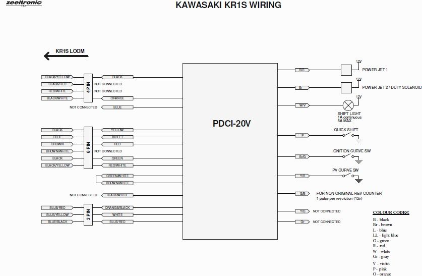
I was looking to use the quick shift function on my Zeeltronic, but the wiring diagram doesn't indicate which wire is used to kill the revs. The zeel wiring diagram is a bit naff.
I have 6 wires coming out;
Purple-White
Green-Black
Green-Yellow
Green
Black-White
Brown-Green
does anyone know which one kills the revs?
I have 6 wires coming out;
Purple-White
Green-Black
Green-Yellow
Green
Black-White
Brown-Green
does anyone know which one kills the revs?
-
KR-1R
- Premix Junkie
- Posts: 1587
- Joined: Wed May 16, 2007 2:24 am
Re: Alternate ign curves
Purple white or white violet is shift light
Green black ... Alternative tacho
Brown green... ign curve selector... Which I think would be a momentary contact type (bush button symbol) not the switch symbol Borut used.
I think your choices are only
black white
Green
Or yellow green
Ask Dan... Black white is ign kill... ? Stop button...
viewtopic.php?f=13&t=7740&p=57022&hilit=brown#p57022
Last edited by KR-1R on Thu Sep 22, 2016 10:40 pm, edited 1 time in total.
-
Luders
- Avgas Sniffer
- Posts: 3926
- Joined: Fri Jun 18, 2010 11:29 am
- Location: Oxfordshire
Re: Alternate ign curves
Just email Borut and ask
-
500bernie

- Avgas Sniffer
- Posts: 3396
- Joined: Mon Aug 02, 2010 10:22 am
- Location: Teesside
Re: Alternate ign curves
The PDCI-20V has a dedicated trigger (pink to ground)

Firecracker Red and Grey C3 300
-
Luders
- Avgas Sniffer
- Posts: 3926
- Joined: Fri Jun 18, 2010 11:29 am
- Location: Oxfordshire
Re: Alternate ign curves
Yeah that's for my ignition Bernie, Tricia's wiring diagram isn't that helpful as she has one of the recommended plug n play ignitions.
-
TwoStroke Institute
- Oil Injector
- Posts: 505
- Joined: Sat Jul 05, 2008 2:17 pm
Re: Alternate ign curves
Quickshift doesn't kill the revs it cuts the spark for the programmed amount of time, just enough to take the load off the gearbox to allow the selection of another gear.scooble wrote:I was looking to use the quick shift function on my Zeeltronic, but the wiring diagram doesn't indicate which wire is used to kill the revs. The zeel wiring diagram is a bit naff.
I have 6 wires coming out;
Purple-White
Green-Black
Green-Yellow
Green
Black-White
Brown-Green
does anyone know which one kills the revs?
Look on the software or controller your have "Shift Kill Time" and a time to enter in milliseconds. All the other 10VT units use the pink wire for the quickshift(the other to ground/earth). The KR-1 the pink is connected to brown/white so it might need to be send back for a reconfigure
crochet & croquet
-
500bernie
- Avgas Sniffer
- Posts: 3396
- Joined: Mon Aug 02, 2010 10:22 am
- Location: Teesside
Re: Alternate ign curves
Hi Trish,
I asked Borut and he replied as follows:
The Pink wire has a double function for KR1S...it is used for neutral/side stand function to kill engine...if you do not need that function, then just disconnect pink wire from the connector and use it for quick shift sensor.
You just have to program kill time between 40-60ms...pink wire has to be switched to the ground to kill engine for programmed time.
Cheers,
Bernie
Firecracker Red and Grey C3 300
-
stevo135+
- Smoker
- Posts: 58
- Joined: Tue Sep 01, 2015 1:23 pm
Re: Alternate ign curves
I'm watching this thread with great interest and looking for info and ideas too.
I've got an ignitec CDI to go onto my KMX 125. I bought all the pc software and link cables to program it, and they have set it up with a fixed 10degree BTDC timing just to get me started.
The reason I'm changing the ignition on a bike with a mechanical power valve is to suit a new One off exhaust I'm having made. I kind of wondered if I could copy the KR1 advance curve just to allow me to safely road test the bike before it goes to the dyno for a professional set up?
Oh and lastly does anyone here think that it's even worthwhile to have a programmable CDI on a bike without an electronically controlled power valve?
-
500bernie
- Avgas Sniffer
- Posts: 3396
- Joined: Mon Aug 02, 2010 10:22 am
- Location: Teesside
Re: Alternate ign curves
Hi Stevo,
There are always improvements to be made on the standard ignition provided by the manufacturer, as they will always be on the safe side (to avoid a million recalls and warranty holed pistons).
If you look at the ignition providers websites you will see that they make them for piston ported engines with no adjustable exhaust valves at all.
So to answer the question, yes it will be worth it, if you are willing to put the time in to get it right.
Was the exhaust pipe specially made to suit the tune of your engine? if so, you could gain more.
Good luck.
Bernie
Firecracker Red and Grey C3 300
-
stevo135+
- Smoker
- Posts: 58
- Joined: Tue Sep 01, 2015 1:23 pm
Re: Alternate ign curves
Hi Bernie.
Yeah I'm slightly excited by the possibility of getting some gains from all the work and expense. My bike is just an unrestricted one with a Fresco pipe currently. On a Dynapro dyno it's made 18.5bhp so far.
The new ignition was ordered because I couldn't find the full CDI ignition map like you guys have managed to determine and plot for the KR1/1S. The pipe will be ready early next year hopefully and it's a total one off and the company doing it has taken all the measurements from my engines porting and specifications to get the best performance.
Im also going up 4mm bore size with a new carb and a Vforce reedblock the same type as you fit to the KR1. To top it all off. I'd like to break over the 20bhp barrier if that's reasonable to expect?
-
500bernie
- Avgas Sniffer
- Posts: 3396
- Joined: Mon Aug 02, 2010 10:22 am
- Location: Teesside
Re: Alternate ign curves
Hi Stevo
Have you done much work to the porting and the crankcases?
Cheers
Bernie
Have you done much work to the porting and the crankcases?
Cheers
Bernie
Firecracker Red and Grey C3 300
-
stevo135+
- Smoker
- Posts: 58
- Joined: Tue Sep 01, 2015 1:23 pm
Re: Alternate ign curves
Hi Bernie.
I havnt really done any engine work on it at all tbh, as I got the bike with a freshly rebuilt engine and didn't want to mess with it too much really. There's a few other reasons too, Firstly the guy doing my pipe said an ideal exhaust and programmable CDI will add some power anyway, without needing to port the cylinder or crankcase for more power at higher rpm than standard.
Secondly I have a BDK tuned and ported 200cc cylinder conversion sat here waiting to go onto the bike at some stage in the future too. I was asked by the dyno centre to check the squish clearance and if possible get it to 0.8-0.9mm for best performance though. I think it's nearer 1.2mm as std from trying to measure it with some bent solder. I've decided to leave it as it is though as when I eventually convert it into a 200 I'll accurately measure and set up the squish with the big bore top end then.
Im hoping the Vforce reedblock and 30mm carb work ok on the 200cc set up too.