How to bypass JDM KR-1S/1R speed restriction...hopefully!

Dodgy Kips motor? CDI? battery? diode? reg/rect? its all gobbledygook to me but some people understand it ask tham a question here
User avatar
James P
Oil Injector
Posts: 582
Joined: Mon Mar 11, 2013 10:47 am
Location: Sydney, Australia

How to bypass JDM KR-1S/1R speed restriction...hopefully!

Post by James P »

This follows on from discussion on the speed restriction of JDM KR-1S and KR-1R models under another topic (viewtopic.php?f=2&t=46569).

After generally keeping an eye out for a 1989 or 1990 JDM KR speedometer for three or four years (and having no success) I got hold of a 1989 ZXR250 speedo instead. This has the same three wires (Brown, Black-Yellow and Pink) as the corresponding KR speedo for a speed limiter switch inside the speedo casing. I reasoned that there may be a chance that the speed limiter switch in the ZXR speedo would work in the same way as that in the KR version. For your general info, the following part numbers apply to OEM JDM speedo units:

1989-90 KR250C1, D1, C2, D2 - 25005-1418
1989-90 ZXR250A1, B1, A2, B2 - 25005-1427

Later ZXR250C (and D) models have a different part number again (25005-1480), but I haven't seen a wiring diagram for any of those models (so I can't confirm that any speed limiter switch wiring is the same as the KR and early ZXR models).
The ZXR speedo I obtained is obviously secondhand (about 33,500km on the odometer), but is in very good condition and seems untampered with.

s.mx51 wrote: Mon Apr 22, 2019 7:37 pm...he took the pink wire and conect it ,to ground wire,with a registor between...
The resistor which Spyros mentioned jogged something in my memory and I returned to the April 1989 KR-1S/KR-1R New Model Guide. After some in-depth translation, I discovered that this booklet seems to contain almost all of the information required to bypass the restriction. Here is a (translated) block diagram of the CDI unit from the booklet:

Image

Sub-assembly No.10 is the speed limiter circuit inside the CDI unit. As you can see, this connects to the speedometer (via the pink wire). The speedo is depicted as a resistor in series with the secondary portion of an opto-coupler, the bottom end of which is connected to earth/frame/negative. Thus, it appears under 'normal' conditions that the pink wire is connected to earth via a resistor. From this, I inferred that when the speedo reaches 180km/h, the sector on the speedo shaft causes the opto-coupler to switch off, thus creating an open circuit between the pink wire and earth. The same effect should be created by unplugging the pink wire, which is what Virgie's experience has suggested.

Reading further in the New Model Guide, I discovered more interesting info (paraphrased from translation): When the voltage at the connection point with the speedo is outside the set voltage range, the ignition timing is fixed at 3 degrees BTDC from 10,100rpm onwards.

The ignition timing at 10,100rpm is normally about 13 degrees BTDC, so retarding it a further 10 degrees is bound to produce a noticeable difference in performance...as Virgie found.

With all the above in mind, I proceeded with testing the ZXR speedo, connecting the wires as follows:
Brown - to positive terminal of 12V DC power supply
Black-Yellow - to negative terminal of 12V DC power supply
Pink - to positive terminal of ohm-meter (i.e. a multimeter on the resistance range)

The negative terminal of the ohm-meter was connected to the negative terminal of the DC power supply (common with the Black-Yellow wire).

I have a laboratory-type 12V AC/DC power supply which I use for checking electrical components and wiring systems. The open-circuit output voltage was 14.5V DC when I checked it before the test.

The first problem I encountered was that I needed to spin the speedo drive shaft anti-clockwise (the right-angled 'gearbox' on the speedo unit does not reverse the direction of rotation as I had first thought). None of my rotary tools equipped with reverse functions would spin fast enough to indicate speeds over about 80km/h, so I resorted to a Dremel Multitool fitted with a nylon wire brush, driving the green plastic gear on the speedo shaft after the right-angled gearbox had been removed. By selecting a medium speed on the Dremel and varying the contact pressure, I was able to gradually increase the speedo indication from zero to about 230km/h (or at least where the 230km/h mark should be).

With the circuit connected, but the power supply switched off, the reading on the ohm-meter was infinity (open circuit). When the power supply was switched on (but the speedo shaft not yet rotating), the meter indicated about 18,000 ohms. This suggests that the opto-coupler switched on when the voltage was applied.
When the speedo shaft started rotating, the reading on the ohm-meter remained fairly steady all the way up to about 185-190km/h, at which point the reading changed to infinity. The infinity reading was maintained with further increase in speed (up to possibly about 230km/h) and then returned to about 18,000 ohms once the speed had dropped below the 185-190km/h point.

The result of the test seems fairly conclusive, suggesting that connecting the pink wire to earth via a resistor of about 18,000 ohms should bypass the restriction.
HOWEVER, remember that I have tested a ZXR speedo, not a KR speedo. The ZXR speedo is obviously different to the KR speedo in some (as yet unknown) way, but this may have nothing to do with the speed limiter switch. It would surely reduce the cost of the speedo for the maker (Nippon Seiki) and the customer (Kawasaki) if the same speed limiter switch was used on as many speedo units as possible.

Notwithstanding the chance to test a JDM KR speedo (or somebody pointing out a flaw in my testing procedure), I would suggest that connecting the '1275' CDI's pink wire to earth via a resistor of about 18,000 ohms should bypass the restriction and make the ignition characteristic the same as the export model '1287' CDI unit.
Despite the unknown factor of any difference between KR and ZXR speedos, it is unlikely that any damage could be done using a reasonably high resistance like that measured.

If Virgie or anyone else is willing to make the connection with a resistor as suggested and let us know what happens, we may be further along the way to closing the book on the matter of derestriction of JDM CDI units.

Regards,
James
User avatar
Virgie
Heavy Smoker
Posts: 282
Joined: Wed Jun 06, 2007 1:48 am
Location: Dartford Kent

Re: How to bypass JDM KR-1S/1R speed restriction...hopefully!

Post by Virgie »

Great stuff James, and I am now going to look into how to find an appropriate 18,000 ohm resistor for automotive use. If any of you guys are auto electricians/engineers and know of a suitable unit please let me know. I am still recovering from my crash at Brands in March with a broken wrist but it is coming along at last. I could do a static test in the next couple of weeks once the repaired swinging arm and rear wheel are back in my bike, but a proper track test will be some time ie I need to be back at work on full duties before I dare go near a track! Then again one of the benefits of being injured is that I will be doing a few test days before I am ready to race again, so will have the opportunity to test the theory without worry of qualifying sessions :P
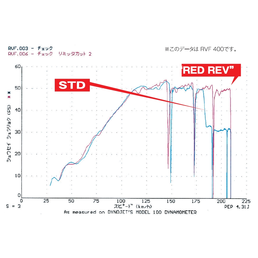
I will update my progress as I get there and thanks again everyone, getting the best out of these CDI's is great news, the unit I have is clearly brand new and unused. I will also try and get the bike to a dyno once I feel the unit is reving out properly so we can see definitively if it will produce the same BHP.
KR-1R
Premix Junkie
Posts: 1587
Joined: Wed May 16, 2007 2:24 am

Re: How to bypass JDM KR-1S/1R speed restriction...hopefully!

Post by KR-1R »

.
.
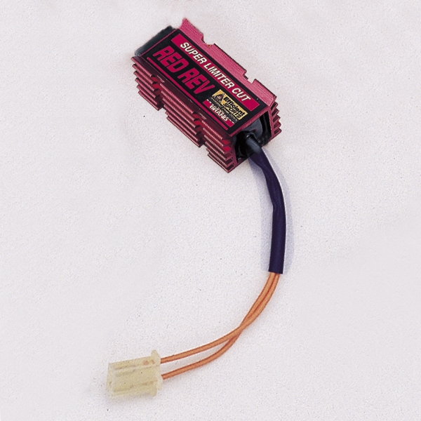
I have a couple of RedRevs for ZXRs.
If i can find them at home i will put an ohmeter across them
User avatar
Virgie
Heavy Smoker
Posts: 282
Joined: Wed Jun 06, 2007 1:48 am
Location: Dartford Kent

Re: How to bypass JDM KR-1S/1R speed restriction...hopefully!

Post by Virgie »

Thanks but what is a RedRevs, I have googled that with no luck apart from a Motorcross shop in the USA! Sounds bike specific from what you have written?
KR-1R
Premix Junkie
Posts: 1587
Joined: Wed May 16, 2007 2:24 am

Re: How to bypass JDM KR-1S/1R speed restriction...hopefully!

Post by KR-1R »

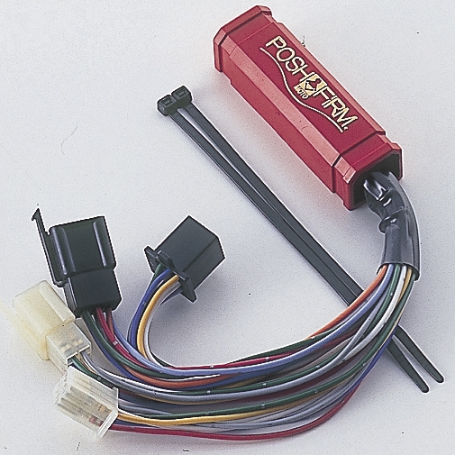
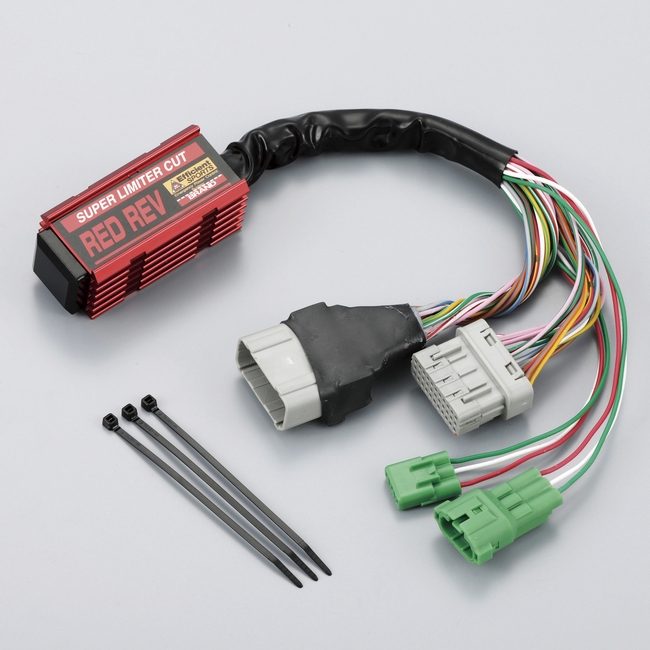
POSH and M-MAX do rev limit derestrictors
Image

https://japan.webike.net/products/21125979.html
on ZXR uncomplicated plugin (2 wire)
Image

more elaborate on other manufacturers bikes
Image
Image
s.mx51
Smoker
Posts: 62
Joined: Sat Sep 04, 2010 5:31 pm
Location: chios greece

Re: How to bypass JDM KR-1S/1R speed restriction...hopefully!

Post by s.mx51 »

hello
nice,well down James P !! :)
User avatar
James P
Oil Injector
Posts: 582
Joined: Mon Mar 11, 2013 10:47 am
Location: Sydney, Australia

Re: How to bypass JDM KR-1S/1R speed restriction...hopefully!

Post by James P »

Virgie wrote: Sat Apr 27, 2019 12:49 pm ...I am now going to look into how to find an appropriate 18,000 ohm resistor for automotive use.
Virgie,

18,000 ohms is a standard value for resistors and anything available from a shop which sells electronic components should do. The small metal film and carbon film type resistors are usually rated at 0.5 watt and 1 watt respectively, which should be ample for this application. Obviously, whatever type of resistor that Nippon Seiki has used on the circuit board inside the speedo, it must be small!
I must admit that I don't know the voltage which the CDI unit applies to the resistor, but it seems unlikely that it would be greater than the output voltage of the rectifier-regulator (i.e. 15V or less). Thus, the current which would flow in the resistor would be about 1 milliamp or less, requiring the resistor to dissipate no more than 15 milliwatts of power. If anyone knows any different, please let us know.

The resistors mentioned above are usually quite cheap and you may even be able to find a pack of ten for about a pound or so. Thus, you can probably assemble a makeshift set-up just to check that this value of resistance achieves the desired effect before making up a permanent box with leads which can be connected between the pink wire and the frame. Whatever permanent arrangement you decide on, just make sure the resistor won't be affected by vibration.

Before we get ahead of ourselves, we should wait for your report on whether the suggested resistance value actually cancels the restriction. Obviously we'll have to wait until both you and the bike are mended to an extent which will allow a dyno run or road test - let us know!

Regards,
James
User avatar
Virgie
Heavy Smoker
Posts: 282
Joined: Wed Jun 06, 2007 1:48 am
Location: Dartford Kent

Re: How to bypass JDM KR-1S/1R speed restriction...hopefully!

Post by Virgie »

That's brilliant and I think a good plan for a simple test with basic parts to check first. If all works I can look into the best way of making a two stroke proof unit!
User avatar
Virgie
Heavy Smoker
Posts: 282
Joined: Wed Jun 06, 2007 1:48 am
Location: Dartford Kent

Re: How to bypass JDM KR-1S/1R speed restriction...hopefully!

Post by Virgie »

I have the bike rebuilt now and have just sent off for a pack of resistors so hope to do some static tests next week. I will let you all know I get on, it should hopefully be fairly obvious if the mod will allow this CDI to fully function.
User avatar
James P
Oil Injector
Posts: 582
Joined: Mon Mar 11, 2013 10:47 am
Location: Sydney, Australia

Re: How to bypass JDM KR-1S/1R speed restriction...hopefully!

Post by James P »

Virgie wrote: Thu Jul 25, 2019 2:59 pm I have the bike rebuilt now and have just sent off for a pack of resistors so hope to do some static tests next week. I will let you all know I get on, it should hopefully be fairly obvious if the mod will allow this CDI to fully function.
Thanks for the info Virgie...waiting for results with bated breath! 8)

Regards,
James
User avatar
Virgie
Heavy Smoker
Posts: 282
Joined: Wed Jun 06, 2007 1:48 am
Location: Dartford Kent

Re: How to bypass JDM KR-1S/1R speed restriction...hopefully!

Post by Virgie »

Ha ha, you havent seen the shocking quality of my soldering yet :lol:
Will it be best to just try and dab the resistor ends (they look awfully skinny on the web site pics) onto a bit of bare wire end that can go to standard bullets/rings at the other end?
As you say I can work out something more substantial later. What I will do is see if I can then get to a dyno and do several runs with the various CDI's I have so we see how all 4 of them are preforming. I have 2x 21119-1287, 21119-1275 and 21119-1234 (for a KR1?) so will be interesting to see if the myth of differences between the same model of CDI in my 2 1287 units is true but also any diferences in power curve with the others.
User avatar
Virgie
Heavy Smoker
Posts: 282
Joined: Wed Jun 06, 2007 1:48 am
Location: Dartford Kent

Re: How to bypass JDM KR-1S/1R speed restriction...hopefully!

Post by Virgie »

Just received the resistors that I hadn't expected until next week. I got 18,000 ohm x 1 watt if that's the guys. They have long 25mm tails for soldering to. Is it ok to wind them around a section of 12v wire before attempting (did I mention not very good :roll: ) soldering or will that alter the resistance values? Thanks Virgie
s.mx51
Smoker
Posts: 62
Joined: Sat Sep 04, 2010 5:31 pm
Location: chios greece

Re: How to bypass JDM KR-1S/1R speed restriction...hopefully!

Post by s.mx51 »

Hello
Kr- 1 cdi 1234.opens the kips 6000-6500 rpm ( i dnot remember exactly which one is) and cuts down the power to 12000rpm to 0 degrees timming
Kr-1s cdi 1287. opens to the kips 7500 rpm and cut off the power to 12000 rpm to 3 degrees
Kr-1r cdi 1275.opens the kips to 8500 rpm and cut off the power to12000 rpm to 3 degrees
Sorry for my English
Spyros
User avatar
Virgie
Heavy Smoker
Posts: 282
Joined: Wed Jun 06, 2007 1:48 am
Location: Dartford Kent

Re: How to bypass JDM KR-1S/1R speed restriction...hopefully!

Post by Virgie »

Thanks Spyros, I will see how that data compares with my runs when I get to the dyno. Will of course put up the graphs for all to see so you can all give your opinions on what happens. And no worries about your English, my Greek is dreadful :lol: :lol: :lol:
User avatar
James P
Oil Injector
Posts: 582
Joined: Mon Mar 11, 2013 10:47 am
Location: Sydney, Australia

Re: How to bypass JDM KR-1S/1R speed restriction...hopefully!

Post by James P »

Virgie wrote: Sat Jul 27, 2019 1:35 pm Just received the resistors that I hadn't expected until next week. I got 18,000 ohm x 1 watt if that's the guys. They have long 25mm tails for soldering to. Is it ok to wind them around a section of 12v wire before attempting (did I mention not very good :roll: ) soldering or will that alter the resistance values? Thanks Virgie
Virgie,

As long as the connection is secure, your suggested 'winding' method should do for test purposes. Any extra resistance introduced by lack of soldering shouldn't make a lot of difference to the overall value of 18,000 Ohms. If you are concerned that the connection may not be secure, you could just apply solder in one spot on each side as temporary insurance (and unsolder it later if/when you are ready to assemble a permanent resistor attachment).

I'm not sure exactly how the CDI units will be positioned for your tests - just try to keep the bare conductors clear of any nearby metal (or perhaps just wrap them with a plastic bag...?).

I wasn't aware that the '1275' and '1287' CDI units had different KIPS opening points as Spyros states, but no doubt you can confirm this during the tests!

Regards,
James
Post Reply