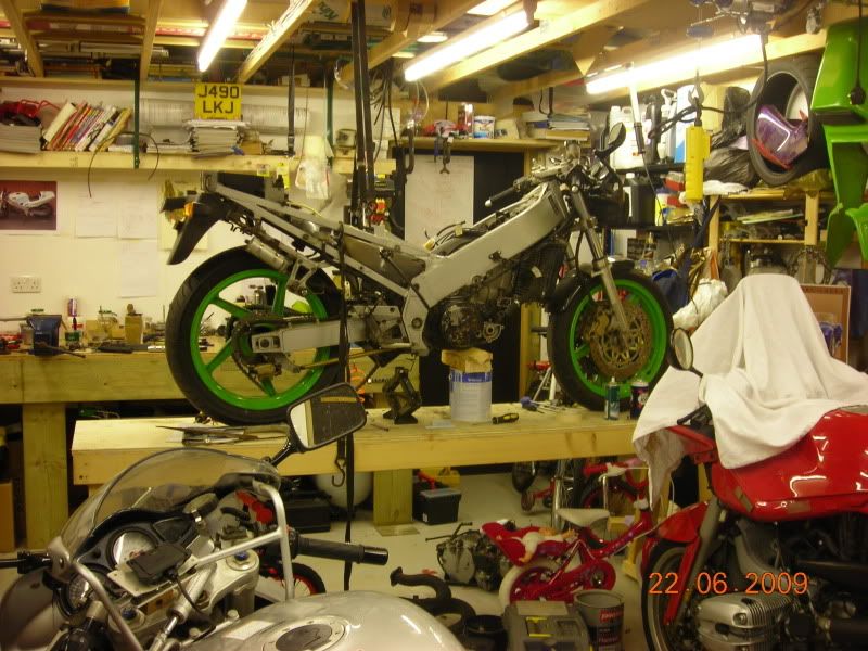
Been moving the engine around trying to get everything in the right place, which has been no mean feat.
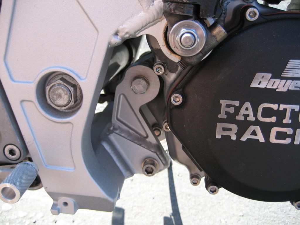
At last I think I’ve got something acceptable. I’d been struggling to get the output shaft high enough so as not to effect the anti-squat characteristics. The problem was whenever I raised the motor the kick start shaft tried to disappear behind the ring side frame spar. Jan’s cunning and therefore will of cheat this by having a roller starter, but I’m intending on using mine on the road and you can guarantee that if I don’t have a kick start I’ll stall it just as I go to pull that one handed 5th gear minger past the girls school!!
It’s ended up output shaft being further forward than before, but the motors not too far forward so I not bothered.
Oh, yeah, and I forgot to mention I don’t want to chop a hole in the spar because I want to be able to go back to original (whether I do or not is another issue, but I want the ability.) Oh, and the other thing is whatever I do can only be made from steel as I can’t weld ally. Ok, I know steel is a dirty word, especially as I’m trying to get the thing as light a possible, but if it all turns out working then I’ll I ask someone to copy my steel work in ally.
Anyway, I finally found a position which seems suitable, and won’t required use of an offset sprocket or anything nasty like that.
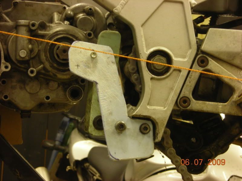
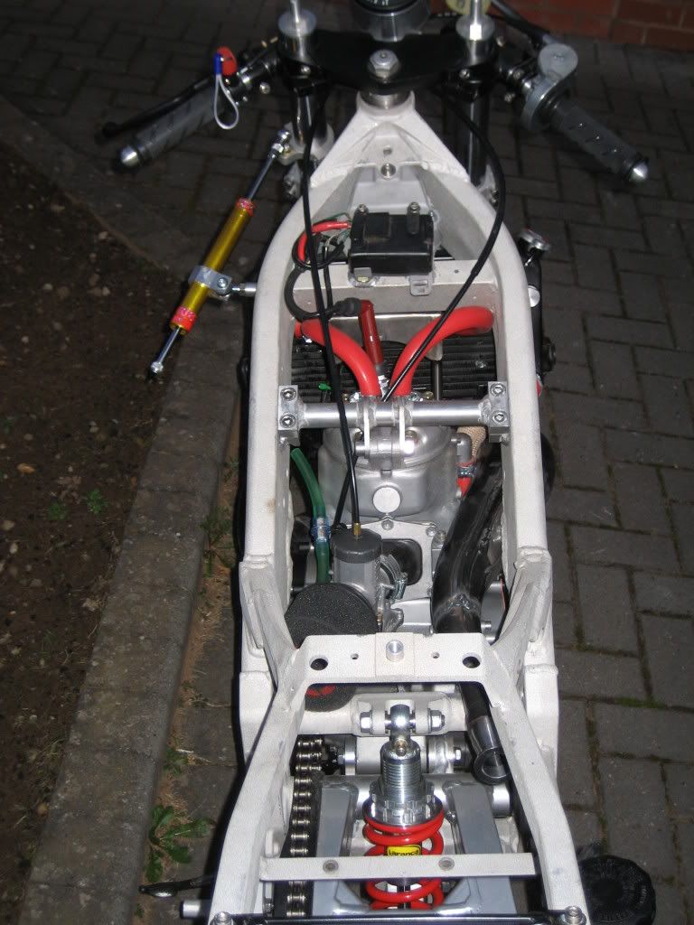
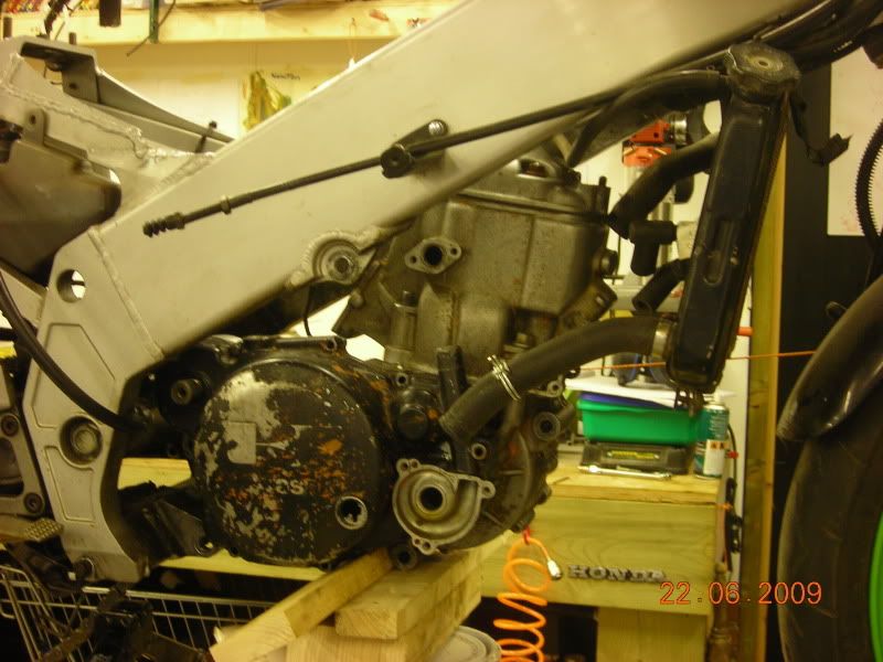
The bit of blue chopping board was cut up to mark where the KR1S output shaft was. That socket head cap screw wound down to touch the end of the shaft on its axis before the old motor was pulled out. The bit of orange string shows a line from rear spindle through swing arm spindle and on at full rear extension. If anyone thinks this is in the wrong place TELL ME NOW PLEASE!
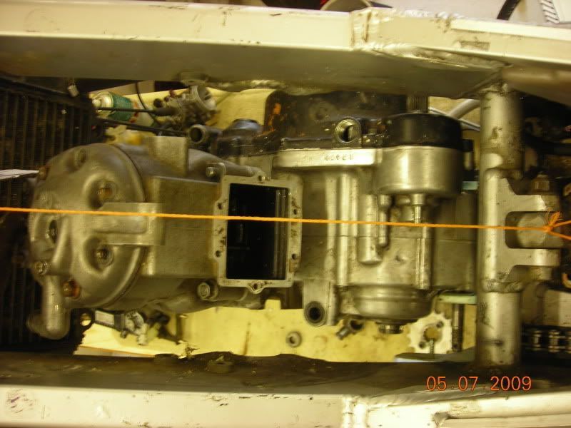
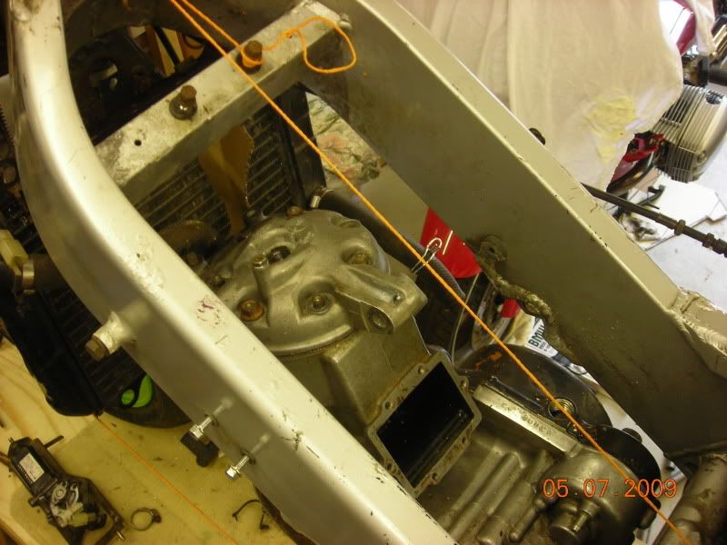
This time the orange string is the centre axis of the chassis. The motor is offset what looks like 12mm from the central axis of the bike, 12mm to the left, but I don’t know that the centre of gravity was on the crankcase split line anyway so I’m happy with it. If it proves a problem then I’ll have to come up with a solution, like the fuel tank holding more fuel on one side than the other or something?
Anyway , like Jans pictures he posted, the engine is going to be housed in a double cradle, but I’m going to use all four of the engine mounts (three on the crankcase and one on e the head) as apart from anything else I don’t trust my welding!
The front end of the cradles is going to be welded to a thick plate which will be bolted onto the front frame brace (that the regulator/rectified bracket bolts to). This looks a bit scrawny to me (confirmed but the extra bracing on Jans chassis), so I’m going to bolt through it to another plate which will be on the other side.
I’m going to go off this plate onto the head steady mount but that is for another day.
The rear ends of each cradle are going to be welded to vertical plate which will mount onto the bottom frame mount, and the rear big motor mount (16mm bolt!)
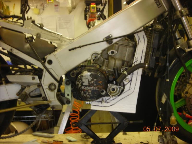
SO with the motor in it proposed position I used card to see where the cradles would go.
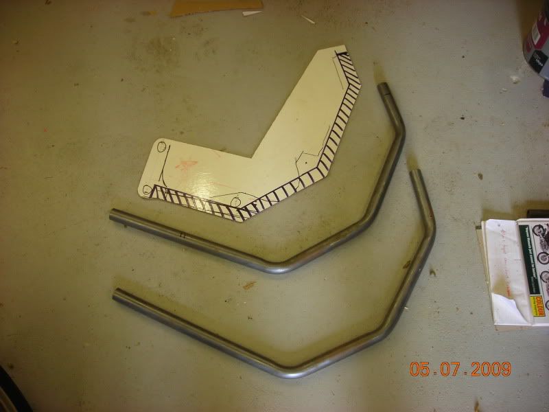
Card board turned to hardboard, which was used as a template to bend 25mm seamless tube as you can see. Tubes were left long so I could have got it a bit wrong.
Since then a lot of standing, looking, thinking and tea drinking has gone on – slow progress but progress all the same - there’s no turning back!


 ..
..