Page 1 of 2
how to set up F3 KIPS valves ?
Posted: Thu Oct 06, 2011 8:27 pm
by JanBros
How do most of you set them ?
Just been busy trying to find out how, but with the standard links, it seems impossible. Since in one cylinder both valves turn the same way, using F3 valves in this setup will mean that one will close the boostport, but the other will not. with the regular valves this isn't a problem.
One solution is to use 2 different valves in one cylindre, so that both ports are properly closed, but that means that in the open position, one bridge is pointing to the inside of the exhaust port, but then that valves acts like a normal valve - and what's more : it's even worse because on the outside, the brigde is missing and so you don't have a smooth passage, but gasses are disrupted because off the cylindrical hole the KIPS sit in.
So how do you guys do this ? just stick them in without thinking ?
Seems like Maccas also thought it through, and he came up with valves turning the opposite direction in each cylindre.
that requires making new links.
Posted: Thu Oct 06, 2011 9:30 pm
by falconman
That is the exact reason I just wired them open on the race bike. Don't need low end to come out of a corner in a straight line race!
Posted: Thu Oct 06, 2011 9:54 pm
by maccas
Yep thats exactly what I thought janbros, i don't think its worth having f3 valves unless you reverse the rotation of the valves.
I also had to make a longer powervalve cable and make the cables cross over, i had to re-drill the pulleys so that they locate on the powervalve stems around 90 degrees round from where they normally locate if that makes sense.
The actual linkages probably aren't too much different in length to the originals to be honest but the ones i have have a fair bit of adjustment for tweaking purposes.
One test i want to do is get the bike warm take it up the road and wind it out to above 8k then kill the ignition then whip the pipes off and double check that all the valves are in the fully open position but i havent got round to it yet.
If i can help in anyway janbros let me know
Maccas
Posted: Sat Oct 08, 2011 9:16 pm
by JanBros
No one ? I thought Charles sold enough to have some feedback

Or doesn't anybody dares to admit they just stuck 'em in without thinking it over


I'm going to stick an F3 valve and an original per cylindre.
Posted: Sun Oct 09, 2011 8:30 am
by ScottaKR
JanBros wrote:I'm going to stick an F3 valve and an original per cylindre.
That's how I did the last motor I put together, although it seems I didn't inspect the crank well enough.

There is a proper way to fit them, but I can never find it when I search the forum.

Posted: Sun Oct 09, 2011 8:35 am
by falconman
I got them in my bike. I had the same problem. When I first installed them and raced the bike went slower. Got home and checked the valves and one was closed the other open. Cycling the pv motor to the open position and they just reversed. I spent a day trying to figure out how to make them work and just gave up and wired them open. Damn the lowend!! Got almost 142mph at the next race. I plan to install the stock ones and open them up and better flow the kips channels for next year. I don't like the missing side. It disrupts flow. I think the F3 valves would work in a stock cylinder when the kips ports are not ported for better flow.
Posted: Sun Oct 09, 2011 12:34 pm
by Rocket
I did almost same as maccas except I used original linkage,
also fitted valves with cutout facing each other in same cylinder,
revolved centre pullys 90 degree, fitted outer pullys backwards,
lenghtened 1 of the cables and swopped cables over at the pullys.
works fine but could do with some adjustable linkage for fine tune.
Posted: Mon Oct 10, 2011 11:34 pm
by JanBros
changed my mind : just gonna put the engine in without the links, and already started designing correct links so the valves work the right way, and put them on when ready.
tried to use the original links on any possible way, but none is satisfactory enough for me
Posted: Tue Oct 11, 2011 11:40 am
by dandan0162
hope you figure it out jan! have some but not fitted them yet,look good though lol
Posted: Tue Oct 11, 2011 11:41 am
by dandan0162
ill take a set of links if you crack it to please [-o<
Posted: Wed Oct 12, 2011 4:11 pm
by JanBros
it's not that hard to figure out how it should be.
the 2 inner valves need to turn the other way round than they do standard. one can switch the 2 cables, but it also can be done very easily electrical

just spent some time in my garage and figured it out

.
the rotation of the motor is determined by the DC voltage : + becomes - to turn the other way round. so you just switch the cables in the connector that delivers the voltage to the engine, it's the one with the 2 wires : switch the blue and black one so the blue is connected to the black on the loom and visa versa (no need to cut any wires if you've never done that : put in a very small screwdriver so the locking-lip is flattenned and you can pull the wire out. the put it back in, just put the lip back up a bit).
now the motor turns the other way round. just the stops don't work properly now. in order to make them work, you need to switch the blue/black and the blue/red wires in the other connector (again with a small screwdriver, but this time, you have to lift the plastic lip to pull the cables out, and just put them back in).
and that's it, now your motor works in the opposite way

drawings of the links will follow when they are done

Posted: Wed Oct 12, 2011 4:30 pm
by maccas
Sounds promising Janbros!
Maccas
Posted: Wed Oct 12, 2011 7:14 pm
by JanBros
these are the links you need :

as you can see, it's actualy a repeat of the middle section of the original links
I'll post dimensions as I'm making them .
kips
Posted: Wed Oct 12, 2011 9:38 pm
by dandan0162
=D> nice one jan,looking forward to it
Posted: Thu Oct 13, 2011 1:41 pm
by 500bernie
Hi Jan/Dan,
I have not assembled mine yet so the sizes of the linkages would be very useful, will you need to make up longer cables? if so can you post the lengths please?
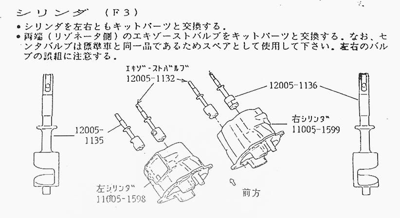
In this Kawasaki drawing, it looks like they used to only put the F3 valves in the outer ports. Is it just me or does the drawings suggest that the valves are fitted with the cutaway facing the outer edge of the barrel, with the solid part closest to the exhaust port?
Cheers,
Bernie