Bit of an irritation; my graphics card burnt itself out yesterday and just when i was making some good progress on the barrels. But every cloud......so ive taken the opportunity to completely upgrade my system including graphics that can actually cope with modern tasks.
Not sure about making it a 300cc, as i'm not at all sure how others have done it in the past. Just widening the bore is possible and i calculated each cylinder to have a 61.5mm diameter bore (or whatever diameter the nearest sized pistons that could be sourced are). Altering the bore and stroke however ,which would means the ratio of bore and stroke could be kept the same, would require modifying the crank which is something i wouldn't even contemplate at this stage.
I doubt i will make an overbore version either as 250 heads and barrels have been/are being time consuming enough but the design i am attempting, with the barrel shell being in two parts with a separate steel liner, should allow for much easier flowing and tuning and along with replaceable combustion chambers might be able to achieve 70hp+ with all the other important tuning mods such as flowed and balanced crank, zeeltronic ignition, improved reed blocks, etc....hopefully.
I have a question for those in the know: What does the chamber on the outside of the barrel do? would the engine benefit from there being a similar chamber on the other side (theoretically)? and is its volume important or is the bigger the better?
I assume it has something to do with the exhaust back pressure from the expansion pipes to prevent unburnt fuel/air from being lost but i can only speculate.
Cheers,
Tofty
the chamber on the outside is to alter the length the gasses have to take....the power is made by a pressure wave re-bounding off the tapered bit at the back of the pipe that returns to the cylinder in time to push back some burning gas(active radicals) to start the burning process and a bit of fuel that hasnt burn back in gettin more in the same volume....as revs rise the time it takes for the wave to re-bound is altered so the power valves allow the gas to go into the chamber before going out the port increasing the effective length of the pipes and altering the time it takes for the wave to return...
long pipe=bottom end
short pipe=top end...
bugger gone cross eyed...
bring a ding ding i'm a throttle happy chappy...
you cant beat a bit of blue haze...
danny harris.....R.I.P
gone but totally forgotten...
A small update:
Still working on the barrels which surprisingly are turning out to be quite a challenge,
however i have completed a few other components (and been able to render them with a bit more quality).
Kit radiator and brackets:
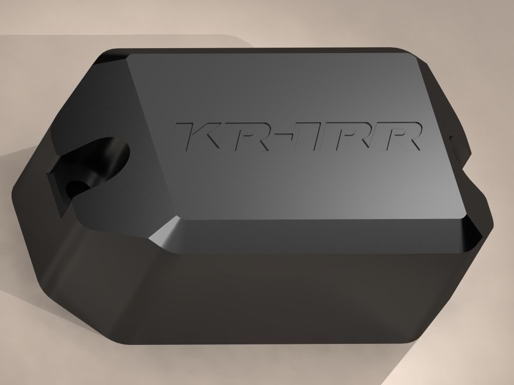
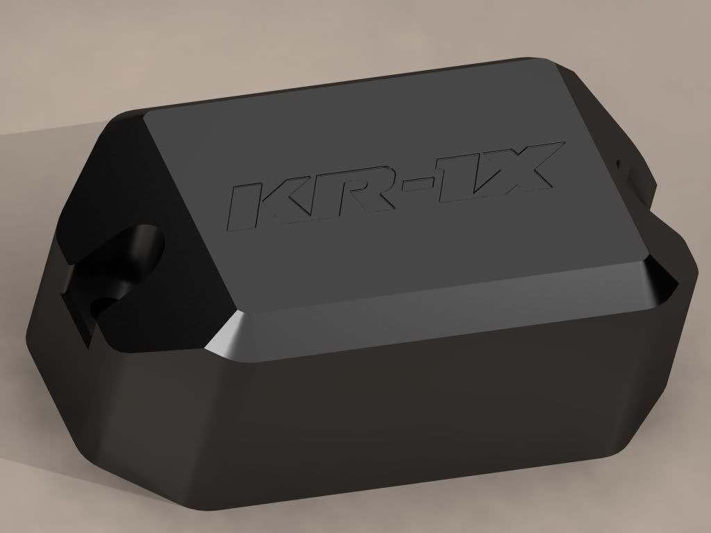
Barrel re-bound chamber:
I'm sure there are much better names for a prototype KR engine than 'KR-1RR' but my mind is blank, any ideas?[/img]
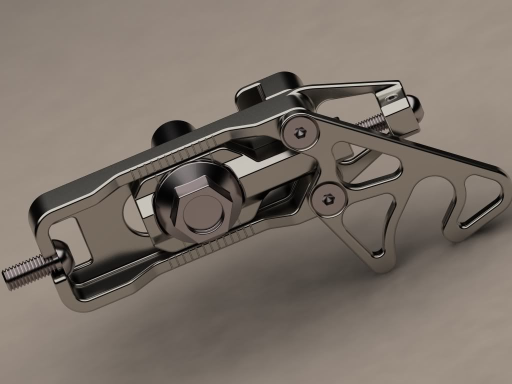
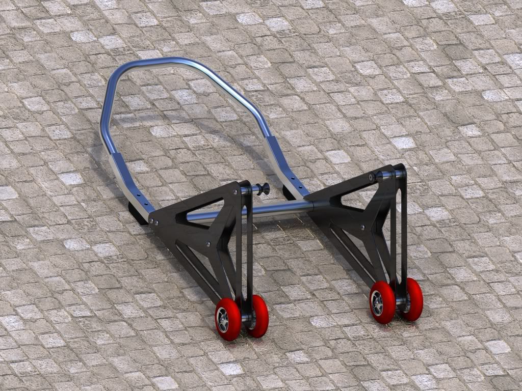
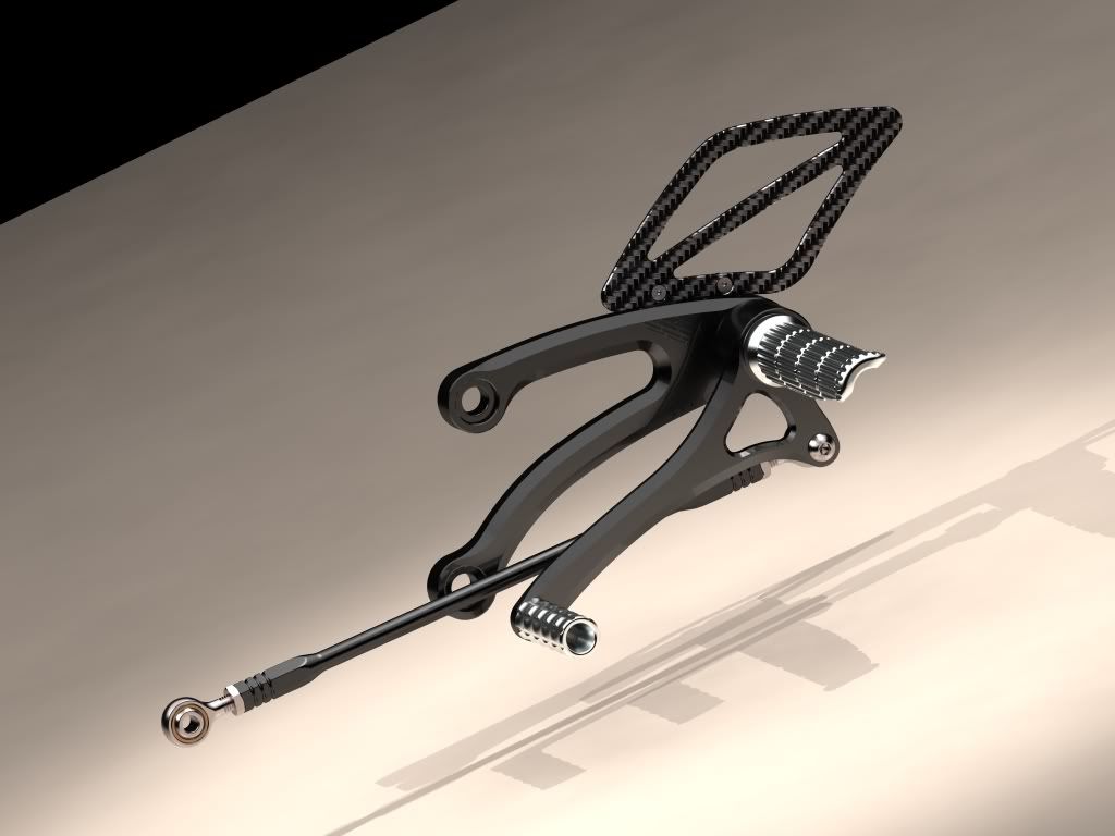
Not really anything to update as far as the barrels are concerned but perhaps i'll have another look at them soonish. Not been completely idle on the; designing expensive and pointless parts front:
Been working on a swingarm modification similar to AlanW's and got distracted.
Anyone got a CNC machinists job going in Surrey for a deluded dreamer?
Looks excellent mate, what program did you model it in? If you can output it as a 3d solids file it can be cut pretty easily. I'm in the toolmaking game and we have the technology.
Not crazy bout the steel barrel liner though, cast iron is probably better imho as it lubricates better. The reason they use coated aluminium is for better heat transfer, how about a nicasil plated Ally liner?
I use Solidworks for all my 3d work (although i draw as much as possible in AutoCAD as its easier) and i believe its not too hard to convert the files into CNC cutting instructions but the parts, especially the head are nowere near good enough to try and machine at the moment.
Now that i come to think about it i'm not sure why i assumed steel liners would be better than aluminium. Using ally would reduce the expansion difference issue at least.
Autocad? I didnt know there was a 3d version....... We do our modelling in Cadkey as solids and export it to surfcam to manipulate it and run cutter paths over the surfaces, what you've already done is probably well good enough for that, that is if it's dimensionally acurate.
In any case you've given me some great ideas for my hotting up my tandem.
Sheik Yerbouti wrote:In any case you've given me some great ideas for my hotting up my tandem.
And another Tandem Twin owner pops up outta nowhere.
So what strange ideas has Tofty's renders given you?
I know it made me wish I could fit KR1S barrels to mine, but the bolt spaceing is wrong (yes, I checked ), so left me thinking about modifying a spare block to take them, but I don't have anywhere near the time or money. Also, it'd be a hell of a lot of work for very little gain,......... but I'd still love to try it.
KR250 Tandem Twin (Naked)
KR1 Red/White
KR1S Track Bike (has been put on hold for now)
ZXR750 H1 (Winter project)
So what strange ideas has Tofty's renders given you?
lol nothing strange, just that old chestnut of more modern barrels on the tandem crank case.
It might be possible to move bolt holes and transfer port entries etc. with an adapter plate. Say 20mm thick, and machine the same thickness from the bottom of the barrel?
Better still to do what Tofty here has done and start from scatch.
Skimming 20mm off the bottom of the barrell will remove the bolt up flange completely.
I was thinking more along the lines of welding up the origional bolt holes in the cases, then drill and tap some new ones.
If you decide to do some custom barells, I'd love to see them.
The other I dea I've had for the tandem engine is doing a 300cc over-bore useing something like RG150 pistons. There's a lot more meat in the tandem barells so wouldn't be as weak after the bore out.
KR250 Tandem Twin (Naked)
KR1 Red/White
KR1S Track Bike (has been put on hold for now)
ZXR750 H1 (Winter project)